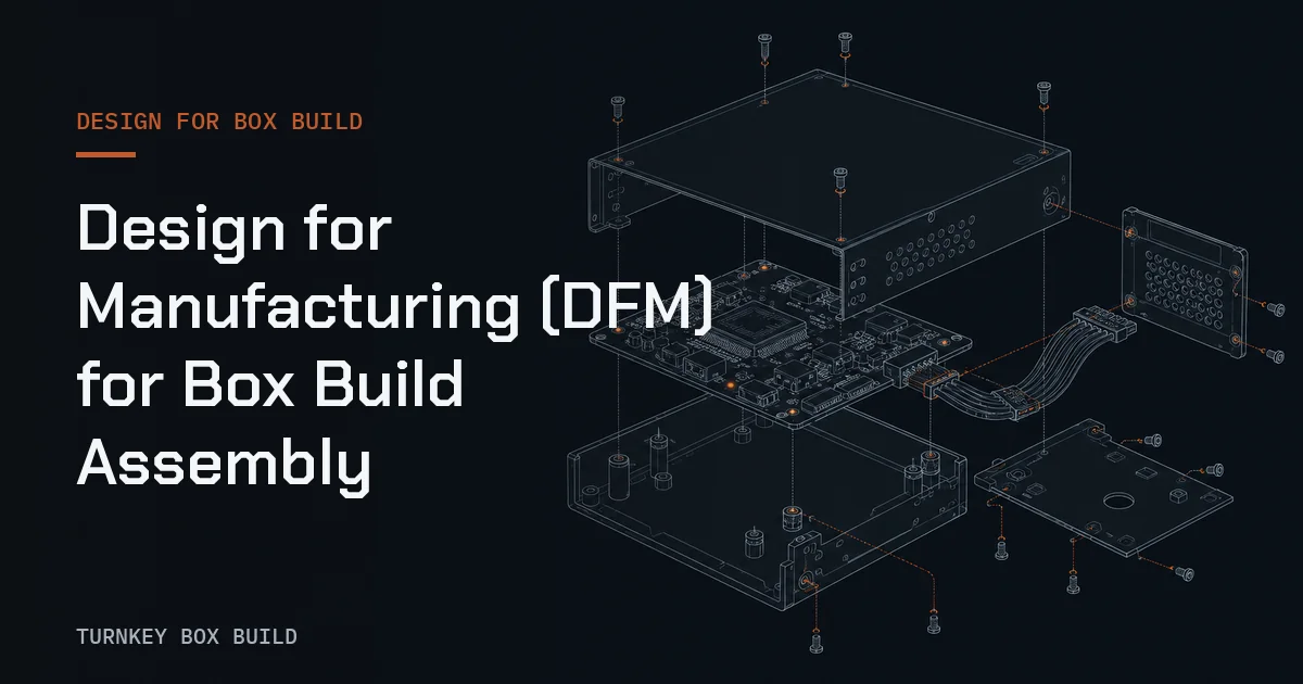
Design for manufacturing for Box Build assembly is a cross-functional review of whether a released product can be assembled, configured, tested, inspected, serviced, and packed as intended. It is broader than checking whether parts fit in an enclosure. A product can fit perfectly in CAD yet force hidden fasteners, damaged cables, uncertain grounding, or a test connector that becomes inaccessible after final closure.
Good Box Build DFM preserves the OEM’s design intent while exposing decisions that manufacturing should not make by assumption. The output is a controlled issue list linked to drawings, models, bills of materials, specifications, and acceptance requirements.
If the system boundary is still unclear, first define what Box Build assembly includes. DFM works best when every participant reviews the same deliverable rather than a different idea of “complete.”
Begin with a stable product baseline
Reviewers need a coherent data set before judging manufacturability. Provide the assembly model, enclosure and bracket drawings, structured bill of materials, connection information, cable drawings, firmware matrix, label artwork, test specification, packaging definition, and revision status. Identify preliminary items and their release owners.
The baseline should state which file governs when formats conflict. A neutral model may support visualization, while a released drawing controls tolerances and finish. The guide to what turnkey means in Box Build assembly also helps define whether the manufacturer coordinates materials or only integrates customer-supplied inputs.
Review interfaces, not isolated parts
Most Box Build problems occur where parts meet. Review enclosure-to-PCBA mounting, bracket-to-panel alignment, connector-to-cutout position, cable-to-edge clearance, thermal pad compression, ground contact to finished surface, and label placement around vents or service areas.
An interface register is more useful than separate mechanical and electrical comments. Each entry should name both sides of the interface, governing documents, required condition, inspection method, and decision owner. The enclosure integration capability shows the kinds of fit, finish, hardware, and grounding details that belong in this review.
Design a feasible assembly sequence
Assembly sequence determines access, product protection, and the ability to verify work before it becomes hidden. Build a proposed route from incoming inspection through kitting, mechanical integration, electrical connection, configuration, test, closure, labeling, and pack-out.
For every operation, ask whether the technician can see the feature, reach it with the approved tool, support the mating part, avoid cosmetic damage, and confirm completion. If a cover blocks a connector check or a cable must be sharply displaced to reach a screw, change the sequence or design before work instructions normalize the risk.
Make fastening and grounding explicit
Fasteners need defined part identity, engagement, sequence where relevant, tool method, and approved joint requirements. DFM should check tool clearance, driver alignment, captive-hardware behavior, thread access, mixed-fastener risk, and whether later operations disturb completed joints.
Grounding deserves separate attention because coating, masking, washers, surface finish, and stack-up can change the electrical path. The OEM should define the intended contact surfaces and acceptance method. Manufacturing should not remove finish or add hardware to “improve” grounding without design approval.
Protect cable routing and connector mating
Cable routing should be defined by functional constraints, not by whichever path appears shortest. Review bend restrictions, strain relief, moving or hot surfaces, sharp edges, clamp positions, service loops, connector polarization, latch access, and separation required by the product design.
The Box Build route should prevent a correctly connected cable from being pinched when the enclosure closes. It should also make incomplete mating detectable. Cable assemblies and PCBAs belong here only as integrated system inputs, with their identity and incoming state defined before installation.
Review thermal intent as an assembly condition
Thermal performance may depend on interface materials, contact pressure, surface cleanliness, orientation, airflow, and the sequence used to mount heat-producing parts. DFM should translate the approved thermal design into buildable controls without creating new design limits.
Specify material identity, placement, protective-film removal, handling, compression indicators if designed, and inspection access. If thermal verification remains a design activity, keep it separate from routine manufacturing acceptance. The production record should prove the agreed assembly state, not claim broader thermal validation.
Design for test and configuration
Test access belongs in DFM because a finished unit may hide the connectors, controls, or measurement points needed for acceptance. Define when programming occurs, how the correct firmware and option set are selected, what fixture connections are required, and whether enclosure closure changes the result.
| DFM question | Risk if unanswered | Preferred output |
|---|---|---|
| Can the station reach test interfaces? | Improvised adapters or partial coverage | Approved access and fixture concept |
| Is configuration unambiguous? | Wrong firmware or option set | Controlled configuration matrix |
| Are pass limits defined? | Operator judgment replaces criteria | Released acceptance rules |
| Can failures be contained? | Failed units re-enter normal flow | Controlled failure route |
| Does closure affect function? | Open-unit pass hides final-state issue | Defined final-state verification |
Use the functional test plan for Box Build to connect requirements, steps, limits, and retained results.
Include inspection and traceability in the design
Inspection is easiest when critical features remain visible and acceptance criteria are objective. Identify which features need incoming, in-process, or final checks and place those checks before later work conceals evidence. Define references for cosmetic zones, labels, connectors, fasteners, routing, seals, and configuration.
Traceability also affects design choices. Leave practical space for human-readable and machine-readable identity, protect labels from wear, and decide which subassembly identities must remain accessible. The Box Build traceability guide helps align fields with investigation needs.
Close DFM issues through controlled decisions
A DFM comment is not closed because the team discussed it. Record the affected requirement, proposed resolution, owner, approval, changed document, and verification evidence. Separate product-design changes from process clarifications so the correct authority reviews each item.
Not every suggestion should be adopted. A change that simplifies assembly may reduce serviceability, shielding, thermal performance, sealing, or user safety. The OEM chooses the trade-off; the manufacturing review makes the consequences visible.
Make DFM part of NPI and quotation
Put the DFM deliverables in the RFQ: baseline inputs, review scope, expected issue format, decision owners, prototype or pilot objectives, and responsibility for document updates. This prevents “DFM included” from becoming an undefined promise.
The Box Build NPI process shows where to verify DFM corrections in a controlled build. For an actionable package, use the RFQ checklist and review the broader Box Build capabilities. When the product baseline is ready, request a quote and ask for a DFM scope review before tooling, material, or pilot decisions are fixed.
The review should carry board-level constraints into PCBA integration and wire, connector, and strain-relief requirements into cable-harness integration. Treating those interfaces together helps expose clashes in access, routing, grounding, and inspection while they can still be resolved through controlled design decisions.