Menu

What We Build

Communication Equipment Box Build Assembly

Integrate approved boards, ports, internal interconnects, configuration, system checks and identity into a complete unit.

  • Controlled port and connector alignment
  • Approved device configuration
  • System verification and serial records

Request a quote

Request a Box Build Scope Review

Send your drawing, BOM or idea — we reply with a practical Box Build scope review.

Need technical help instead? Contact support

What Communication Equipment Builds Usually Involve

Communication equipment can combine a chassis or enclosure with approved processing, switching, radio, timing, power or interface PCBAs; backplanes or modules; fans and thermal parts; front-panel controls and indicators; internal data, power or RF interconnects; and external ports. The complete Box Build aligns these mechanical and electrical interfaces, applies approved software or settings, checks the finished configuration and prepares the identified unit for delivery.

Products may differ greatly in architecture, data rate, protocol, channel count, radio content and installation environment. These characteristics come from the customer-controlled design and test package. We integrate, test and deliver against that released definition without turning a product category into a blanket performance or compliance claim.

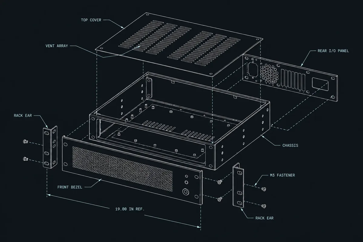
Exploded communication equipment blueprint showing a chassis, approved boards, modules and external interfaces

Typical Integration Scope

Chassis and interface presentation

The approved chassis, panels, card guides, brackets, shields, bezels, handles, rails and hardware establish the mechanical platform. Enclosure integration coordinates external port alignment, module insertion, indicator visibility, fan openings, grounding contact and access for assembly, test and service.

Boards, modules and power

Approved main boards, interface cards, radio modules, power supplies, fans and thermal interfaces are installed with controlled identity and orientation. PCBA integration covers mounting, isolation, connector mating, grounding, support and the programming or test access required in the assembled unit.

Data, power and RF interconnects

Internal cables and harnesses follow the released endpoint and routing plan. Integration checks connector seating, keying, polarity, bend radius, retention, strain relief, separation, shielding or grounding details, and routes near fans, sharp edges, heat sources or removable modules.

Configuration and pack-out

Approved firmware, network parameters, feature settings or module configurations can be loaded through a controlled process. Serial, MAC or other unit identity is applied from approved rules, followed by labels, accessories, cables, manuals and transport packaging defined for the shipment.

Engineering and Verification Considerations

Communication products connect dense interfaces, thermal management, grounding, software and unit identity. Build instructions and tests should preserve the relationships among those inputs across each approved variant.

Interface, thermal and EMC context

Port fit, shielding contact, cable placement, airflow, fan direction, thermal-interface installation, fastener access and module retention may be critical to the approved product configuration. EMC, radio, safety and market-access performance remain customer-owned design and compliance matters unless a different responsibility is expressly documented.

Configuration and system checks

The functional-test plan can include approved power-up, boot, indicator, port-presence, link, communication or selected traffic checks. The customer defines topology, counterpart devices, fixtures, software, limits, expected results, test data and failure handling. Assembly alone does not establish network or RF performance.

During NPI and pilot production, the team can confirm module and port access, cable routing, airflow direction, configuration steps, identity allocation, test execution and protective packaging. Approved changes then follow the stated ECO or ECR effective point.

What to Include in the RFQ

Provide the current hardware, software and test definition together. Mark working revisions and identify which decisions must be closed before quotation or build release.

Mechanical and material inputs

BOM, approved sources, chassis data, assembly and panel drawings, module list, thermal parts, variants and supply responsibility.

Connection and interface data

Board revisions, backplane definition, harness or cable drawings, port map, RF interfaces, grounding, shielding and power requirements.

Software and identity rules

Approved images, settings, loading access, device or network identifiers, allocation method, data protection and required configuration records.

Verification and delivery

System-test procedure, topology, fixtures, limits, compliance responsibility, labels, accessories, packaging, quantity, forecast and handover format.

Review the full RFQ checklist, explore the complete capability map, or return to all product types.

Ready to Review Your Box Build Scope?

Have a BOM, assembly drawings, enclosure CAD, harness requirements or test procedure? Send what you have. We’ll confirm the Box Build scope, identify missing information and outline the next step before quotation.