Menu

What We Build

Custom Electronic Subsystems Box Build Assembly

Turn a defined mechanical and electrical subsystem into a tested, identified and documented delivery item.

  • Clear subsystem boundary
  • Coordinated mechanical and electrical inputs
  • Defined test and handover

Request a quote

Request a Box Build Scope Review

Send your drawing, BOM or idea — we reply with a practical Box Build scope review.

Need technical help instead? Contact support

What Custom Electronic Subsystem Builds Usually Involve

A custom electronic subsystem is a defined delivery item that combines mechanical structure, approved PCBAs, internal cables or harnesses, purchased electromechanical components, interfaces, software or configuration, test, identification and packaging. It may install into a larger machine, cabinet, vehicle, instrument or product, but it can still be managed as a complete Box Build when its boundary and acceptance condition are clear.

The first task is to define what belongs inside the subsystem and what remains with the customer's final product. Mating connectors, mounting points, power and signals, software dependencies, cooling, communications, test access, compliance responsibilities and handover records should be stated at that boundary. We then integrate, test and deliver the approved scope.
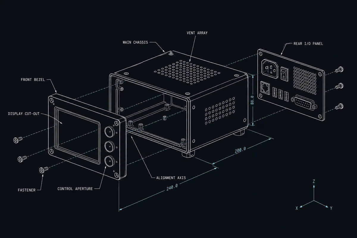

Exploded custom electronic subsystem blueprint showing coordinated mechanical, board and cable interfaces

Typical Integration Scope

Mechanical assembly

The approved enclosure, chassis, frame, panels, brackets, mounts, seals, thermal parts and hardware form the subsystem structure. Enclosure integration coordinates internal fit, openings, external mounting, connector presentation, grounding points, closure sequence and service access.

Electronics and purchased components

Approved PCBAs, power devices, sensors, actuators, switches, displays, fans, terminals or COTS modules are installed to the released configuration. Electromechanical assembly controls part identity, orientation, mounting, isolation, fastening and interface contact.

Internal wiring and interfaces

Harnesses, cables and point-to-point connections follow approved drawings or connection maps. Routing, connector seating, polarity, keying, retention, strain relief, bend radius, shielding, grounding and labels are checked where specified, including the interface leads presented to the parent product.

Configuration and delivery state

Approved firmware, parameters or device settings can be loaded and recorded. Unit labels, serial identity, protective covers, loose accessories, interface caps, documents and packaging are applied so the delivered subsystem matches the agreed installation and receiving condition.

Engineering and Verification Considerations

Subsystem work depends on disciplined interface control. An internally correct assembly can still fail at the parent-product boundary if mechanical, electrical, software or data assumptions are not explicit.

Interface control and variants

Interface drawings should define mounting datums, envelopes, keep-outs, mating parts, pinout, power characteristics, grounding, thermal paths, communication behavior and installation orientation. Variant matrices should connect each deliverable option to its BOM, drawings, firmware, labels, accessories, test revision and serial rules.

Standalone and parent-system verification

The functional-test plan should distinguish checks possible on the subsystem from tests that require the parent product or a customer-defined simulator. It must identify fixtures, software, stimuli, expected responses, limits, data fields, known dependencies and authority for failures, rework and retest.

For a new or materially changed subsystem, NPI and pilot builds can verify the interface definition, assembly sequence, fit, routing, configuration, standalone test and installation packaging. Findings remain open until approved changes are released into all affected files.

What to Include in the RFQ

Start with a short subsystem boundary statement, then provide the technical package and required delivery evidence. Incomplete inputs can be reviewed when their status and owners are clear.

Boundary and product definition

Intended function, parent-product interface, BOM, approved sources, assembly drawings, enclosure data, variants and customer-supplied items.

Mechanical and electrical interfaces

Mounting and envelope drawings, mating connectors, pinout, harness data, power, grounding, thermal, communication and installation requirements.

Configuration and verification

Approved software, settings, loading method, inspection and test procedures, fixtures, simulators, limits, records and compliance responsibility.

Identity and handover

Serial rules, label artwork, accessories, protective interfaces, documentation, packaging, quantity, forecast, timing and final delivery condition.

Prepare the full RFQ package, review Box Build capabilities, or return to all product types.

Ready to Review Your Box Build Scope?

Have a BOM, assembly drawings, enclosure CAD, harness requirements or test procedure? Send what you have. We’ll confirm the Box Build scope, identify missing information and outline the next step before quotation.