Menu

What We Build

Robotics Controllers & Automation Cabinets Box Build

Integrate approved drives, controllers, safety and I/O devices, internal wiring, panel interfaces, configuration and verification into a defined finished control cabinet.

  • Drive, PLC and motion-controller integration
  • Segregation, grounding and thermal handled to the drawing
  • Project-defined I/O and communication checks

Request a quote

Request a Box Build Scope Review

Send your drawing, BOM or idea — we reply with a practical Box Build scope review.

Need technical help instead? Contact support

What a Robotics Controller or Automation Cabinet Build Involves

Short answer: a robotics controller or automation cabinet is a controlled assembly that brings the enclosure and back-panel together with approved motion and logic electronics — PLCs or industrial PCs, servo and stepper drives, VFDs, motion controllers, safety relays and E-stop circuits, power supplies, I/O modules, terminal blocks, contactors and an HMI — plus the internal harnesses, DIN rail, wire duct and external interfaces that connect them. Our role is to integrate the approved inputs to the released definition, verify the finished cabinet against the customer’s acceptance plan, and hand it over in the agreed condition.

Two things make these cabinets different from a general control box. First, drives and servos are strong EMI sources, so power, motor, signal and communication routing has to follow the approved segregation and grounding scheme instead of the shortest path. Second, the assembly sequence is tight: once rails, ducts, drives, busbars and harness branches are populated, access for fastening, connector mating, bonding and inspection narrows quickly. A build plan that respects both keeps the unit repeatable and serviceable.
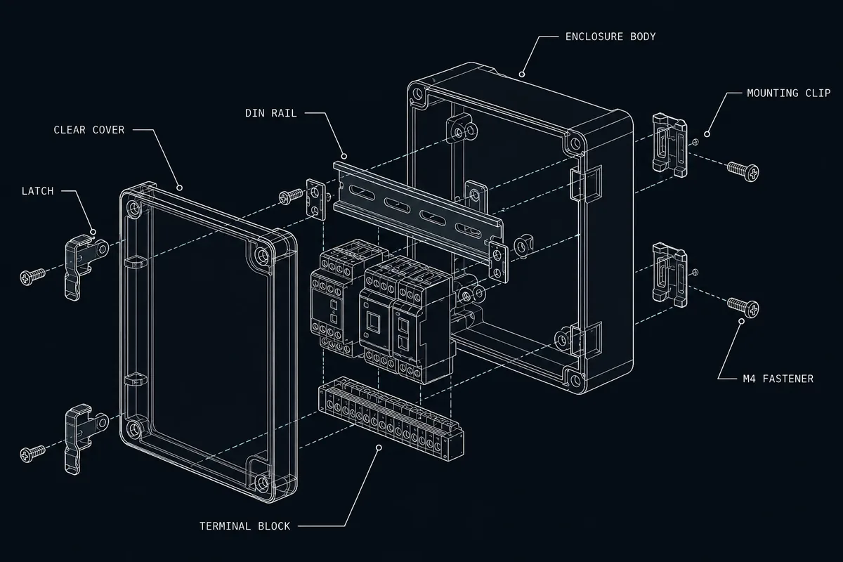

Exploded blueprint of a DIN-rail automation cabinet showing the back panel, mounted drives and controllers, wire duct and internal interconnections

Typical Integration Scope

Back panel and mechanical platform

We prepare the approved enclosure and back panel, then install DIN rail, wire duct, mounting plates, standoffs, bonding studs and door hardware. Cable-entry glands, cutouts and door-mounted HMI or E-stop presentation are checked as part of enclosure integration.

Drives, controllers and I/O

Approved PLCs or IPCs, servo/stepper drives, VFDs, motion controllers, safety relays, power supplies and I/O modules are mounted to the released layout. Board-level items follow the PCBA integration scope; heat-producing drives are positioned for the airflow and clearances the design calls out.

Internal wiring and interconnections

Motor, power, signal and fieldbus wiring follows the approved connection map and segregation scheme — separation from drive outputs, shield termination, bend radius, strain relief, labels and service loops. Connection and polarity checks are defined with the cable-harness integration package.

Configuration and final delivery

Where required, approved PLC programs, drive parameters or firmware are loaded and recorded. Cabinet labels, wiring-diagram pockets, serial identity, warnings, accessories and protective packaging are applied to customer-approved files before the finished assembly is released.

Engineering and Verification Considerations

Review for these cabinets focuses on the interfaces that affect assembly repeatability, electrical safety and finished-unit behavior. Requirements are not inferred from the fact that a cabinet drives motion — they must be defined by the drawings, connection diagrams, specifications and the customer-approved acceptance plan.

EMC segregation, grounding and thermal

The design should define power/signal separation, shielded-cable termination, protective-earth and functional-earth bonding, and the ventilation, fan or filtered-airflow path that removes drive heat. Cabinet-level EMC, LVD and machinery-safety certification remain the product owner’s responsibility and should be assigned in the responsibility matrix, separate from assembly verification.

Finished-cabinet test

A project may require insulation or continuity checks, defined power-up behavior, safety-circuit and E-stop verification, drive enable/disable states, indicators, and selected I/O or fieldbus communication checks. The functional-test package must state setup, fixtures, limits, expected responses, pass/fail rules, data capture and the route for failures, rework and retest.

For a new or changed cabinet, an NPI or pilot build exposes access, routing, sequence and test issues before repeat production. Approved findings feed back into the BOM, drawings, work instructions and verification package. These cabinets sit close to our industrial control boxes and power control systems scope, so shared components and test steps can be reused where the products overlap.

Example: Supporting a Robotics OEM Rollout

An Asia-Pacific robotics OEM (Singapore) needed PCB assembly and integration support for a product rollout, structured as a multi-PO program with split deliveries and time-sensitive schedules. One split purchase order faced a tight-timeline risk. We managed it with proactive order handling — same-day payment confirmation and an early delivery-timeline warning on the constrained PO, while confirming the other POs stayed on schedule.

The result was schedule transparency across the program and no delivery disputes — the kind of order discipline that matters when a robotics build depends on several sub-deliveries arriving in sequence. (Anonymized at the customer’s request; commercial details generalized.)

What to Include in the RFQ

Send the current product definition and mark preliminary information clearly. The most useful package explains both the physical build and the evidence required at handover.

Product and material definition

BOM, approved sources, quantities, variants, cabinet and back-panel drawings, layout, and a list of customer-supplied items such as drives, controllers or the HMI.

Electrical and software inputs

Connection and single-line diagrams, segregation and grounding requirements, PCBA and harness revisions, PLC programs, drive parameters, firmware and programming access.

Verification and compliance boundary

Inspection criteria, functional and safety-circuit test procedure, fixtures, acceptance limits, required records, and ownership of cabinet-level EMC, LVD and machinery-safety certification.

Identity and delivery

Serial rules, label and wiring-diagram artwork, accessories, manuals, packaging, delivery condition, build quantity, forecast and requested timing.

Use the complete Box Build RFQ checklist or return to all product types.

Ready to Review Your Box Build Scope?

Have a BOM, assembly drawings, enclosure CAD, harness requirements or test procedure? Send what you have. We’ll confirm the Box Build scope, identify missing information and outline the next step before quotation.