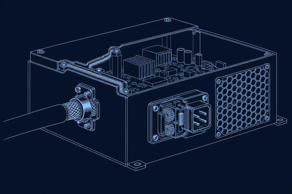
An enclosure only shields as well as its worst opening. A solid metal shell blocks electromagnetic fields, but real boxes have seams, vent holes, display windows, and cable entries, and the field leaks through whichever of these is largest relative to the wavelength. EMC (electromagnetic compatibility) is a system property of the finished box: the shell, its joints and gaskets, the cables that cross its boundary, the filters on those cables, and how everything is grounded. It is decided in the design and then protected or damaged on the assembly line.
This guide covers where a box leaks, a rule of thumb for sizing openings, gasket and finish choices that keep a seam conductive, how to terminate cable shields and bond panels, what the assembly process contributes, and what to put on your drawing. It is general engineering guidance: which EMC standards apply and whether the product passes remain the OEM’s responsibility, verified by testing.
Where an enclosure leaks
Think of the enclosure as a shield with a list of holes. In a typical box build the leaks come from five places:
| Leak path | Why it leaks | Typical fix |
|---|---|---|
| Seams and joints | Two panels that touch only at screws leave slots between the fasteners | Conductive gasket or fingerstock, closer fastener pitch, overlapping flanges |
| Vents and openings | Large holes pass fields; airflow and shielding pull against each other | Many small holes or a honeycomb panel instead of one large opening |
| Display and window cut-outs | A transparent opening is an open aperture | Conductive mesh or coated glass behind the window |
| Cable entries | An unshielded cable acts as an antenna through the wall | 360° shield termination at the wall, filtered connectors, ferrites |
| Bonding gaps | Panels that are not electrically bonded float and can re-radiate | Short, wide bonds and bare, conductive contact surfaces |
The wavelength rule for openings
A slot or hole leaks efficiently when its longest dimension approaches half a wavelength. A common design rule of thumb is to keep the longest dimension of any opening below about one twentieth of the wavelength (λ/20) at the highest frequency you need to shield. The wavelength in free space is λ = c ÷ f, so λ in millimetres is roughly 300 ÷ f, with f in GHz.
A worked illustration, using the rule of thumb and a simple single-slot estimate, not a measured result:
| Frequency | Wavelength λ | Longest opening at λ/20 | Estimated shielding of one slot, 20·log(λ ÷ 2L) |
|---|---|---|---|
| 300 MHz | 1,000 mm | 50 mm | about 20 dB for a 50 mm slot |
| 1 GHz | 300 mm | 15 mm | about 20 dB for a 15 mm slot |
| 1 GHz | 300 mm | 5 mm | about 30 dB for a 5 mm slot |
Two lessons. First, the longest dimension matters, not the area: a thin 100 mm seam gap leaks like a 100 mm slot. Second, many small holes beat one large one, which is why vent panels use a honeycomb or a perforated pattern rather than a single cut-out. This estimate is idealized and real shielding depends on the material, the gasket, and the cabinet resonances, so treat it as a sizing guide and confirm by test.
Seams and gaskets
Seams are usually the biggest leak, because every joint between two panels is a long slot. Close it with a conductive gasket (conductive elastomer, knitted wire mesh, fabric-over-foam, or spring fingerstock) that keeps the two faces in electrical contact along the whole joint, and keep the fastener spacing small enough that the unsealed gap between screws stays short by the same wavelength logic.
Three practical points decide whether the gasket works:
- The mating faces must be conductive. Paint and standard anodizing are insulators. The contact area needs to be bare metal or a conductive finish such as a conductive chemical conversion coating.
- Compression has to be right. A gasket works over a defined compression range. Too little leaves gaps; too much takes a permanent set or damages the groove. The flange stiffness and fastener count set whether it compresses evenly.
- Check galvanic compatibility. In humid or outdoor environments, a gasket filler and a housing metal that are far apart in the galvanic series corrode at the contact. Match the gasket to the housing metal and the sealing requirement; the same seam may also need to carry an IP rating, so choose a gasket that handles both.
Material and process choices
Sheet steel and aluminium shield well on their own and are the usual choice when shielding is a hard requirement. Plastic enclosures are transparent to fields, so they need a conductive coating, paint, metallization, or conductive-filled plastic, each with its own cost, adhesion and durability limits. The trade-offs are covered in our guide to sheet metal versus injection molding for enclosures; if shielding is required, state it before the material is chosen rather than after tooling is cut.
Vents are where shielding meets heat. A sealed shielded box has the same cooling limits described in thermal management in enclosures, and a honeycomb vent panel can pass air while staying small relative to the wavelength. Settle airflow, shielding and IP rating together.
Cables, filters and shield termination
Most real-world EMC failures come through cables, not through the shell. A cable that crosses the enclosure wall carries noise in and out unless it is treated at the boundary:
- Terminate shields 360° at the wall. Connect the cable shield to the chassis around its full circumference with a shielded backshell, a clamp, or a bulkhead gland. A long wire pigtail adds inductance and loses most of its effect at higher frequencies.
- Filter at the boundary. Feedthrough filters, filtered connectors or common-mode chokes at the point of entry keep noise from entering the enclosure along signal and power lines.
- Use ferrites as a fix, not a design. A clamp-on ferrite can reduce common-mode noise on a cable, but it is a tuning tool; a properly terminated shield is the foundation.
- Segregate noisy and quiet cables inside. Route power and switching lines away from sensitive signals. Cable routing is part of EMC design, which is one reason cable harness integration is planned with the layout.
For the internal paths leading to those shield terminations, cable management and wire routing in enclosures covers power-signal separation, crossings and repeatable fixing locations.
Bonding and grounding
Every conductive panel, door, and bracket should be electrically bonded to the chassis through a low-impedance path. Prefer short, wide bonds (a short, wide strap has far lower inductance than a long thin wire), and remove paint or anodizing under the bond point so the metal actually touches. Star washers or a bonded stud help the connection survive vibration. Decide up front how signal ground relates to chassis: single-point, multi-point, or a hybrid depends on the frequencies involved, and the electrical design should state it.
What the box-build process contributes
A shielding design on paper depends on the assembly line to deliver it:
- Gasket seating: the gasket must be fully seated in its groove and uncut, and compressed evenly.
- Fastener torque and sequence: a defined tightening order and torque keep contact pressure uniform around the seam.
- Bonding-surface preparation: paint and finish must be cleared from the bond points the drawing calls out.
- Shield termination workmanship: the 360° termination, clamp or backshell has to be assembled the same way every time.
- Cable routing: noisy and quiet cables kept apart, and bundles not draped across apertures.
- Verification: where the drawing sets a limit, a bonding-resistance check across seams or to the chassis confirms the connection.
These controls are part of design for manufacturing on a box build and are checked during enclosure integration, where the shell, gaskets and fastening are reviewed together.
Testing and compliance
EMC verification is done on the finished product. Emissions and immunity requirements depend on the product category and the markets you sell into, so the OEM selects the applicable standards (for example CISPR and IEC 61000 series test methods) and carries the compliance file; final testing is performed by an accredited laboratory. A pre-compliance check with near-field probes or a quick scan during development finds leaks cheaply, long before the formal test. For how the finished unit is exercised during build, see our guides to box build testing types and the functional test plan.
What to put on your drawing and RFQ
- The EMC requirement: applicable standards, frequency range of concern, and whether shielding is mandatory or only desirable.
- Enclosure material and finish, including which faces must stay bare or conductive for gasket and bonding contact.
- Gasket type, location and compression requirement, and the fastener count and torque.
- Bond points: where panels and doors are bonded to the chassis, and the method (strap, stud, star washer).
- Cable shield termination method at each entry and the connector or gland to use.
- Filters and ferrites: which lines are filtered, with the part numbers.
- Apertures: the size and pattern of vents and window treatment.
- Verification: the bonding-resistance limit or inspection point you want checked on every unit.
Shielding is decided at the drawing: the best result comes from stating the EMC requirement early, choosing shell, gasket and finish together, terminating every cable shield at the wall, and verifying the finished box by test. If you are building a control, power or communication product, our work on power and control systems and EV charging station enclosures regularly involves this trade-off between shielding, sealing and heat.
For how the EMC environment, DIN rail layout and 24 V DC supply fit together in a plant enclosure, see box build for industrial automation.