Menu

What We Build

Power Control Systems Box Build Assembly

Coordinate approved power, control, wiring, thermal and protection elements within a defined complete-unit build.

  • Controlled power-component integration
  • Defined grounding and routing
  • Project-specific verification

Request a quote

Request a Box Build Scope Review

Send your drawing, BOM or idea — we reply with a practical Box Build scope review.

Need technical help instead? Contact support

What Power Control System Builds Usually Involve

A power control system Box Build can combine an enclosure or chassis with approved power supplies, conversion or distribution modules, control PCBAs, contactors, relays, protection devices, terminal blocks, sensors, fans, heat sinks, switches, indicators and internal interconnections. We integrate the released items into the defined mechanical and electrical arrangement, apply approved configuration, perform specified checks and deliver the documented unit.

Because voltage, current, stored energy and heat can create product-specific risks, the customer must define the design requirements, ratings, protective architecture, safety and compliance plan, and acceptance criteria. Correct assembly supports that approved design but does not replace product validation or certification. Related power-focused builds include energy storage / BESS enclosures and EV charging station enclosures.
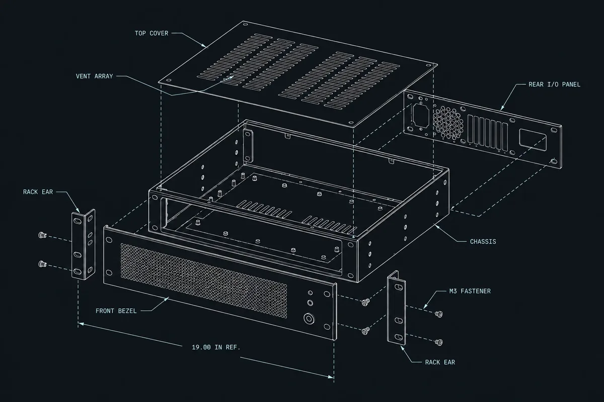

Exploded power control system blueprint showing the chassis, approved electronics and internal power interfaces

Typical Integration Scope

Enclosure and mounting structure

We integrate the approved housing, panels, rails, brackets, bus supports, barriers, insulators, seals and fastening hardware. Enclosure integration checks openings, component fit, cover clearance, grounding locations, cable entry and the access needed for assembly, inspection and service.

Power and control components

Approved PCBAs, power modules, relays, contactors, breakers, terminal blocks, fans and thermal parts are installed to the released layout. Mounting orientation, isolation, fastening, interface contact and part identity are controlled through the assembly definition.

Internal wiring and grounding

Cables, harnesses and approved conductors are routed and connected according to the supplied diagrams. The harness integration plan covers endpoint identity, polarity, retention, strain relief, separation, bend radius, protective sleeving, labels and customer-defined grounding or bonding details.

Configuration and final presentation

Where the product requires software or adjustable device settings, the approved values are loaded and recorded. Unit identification, warning and interface labels, covers, accessories, documents and transport protection are then applied in the agreed final configuration.

Engineering and Verification Considerations

Power-system integration requires explicit criteria. Drawings and specifications should identify characteristics that cannot be determined from the BOM alone, and the responsibility matrix should separate assembly checks from design validation.

Clearance, heat and protection

The released design should define electrical spacing, barriers, insulation, protective-earth or bonding points, conductor sizing, terminal requirements, airflow, thermal interfaces, touch protection and enclosure access. Any critical fastening or connection requirement needs an acceptance method and a clear record expectation.

Safe, defined test conditions

The functional-test package must specify fixtures, interlocks, sources, loads, setup sequence, limits, expected behavior, data fields and failure handling. Safety, dielectric, grounding or load tests are included only when the approved method, equipment responsibility and acceptance authority are explicitly agreed.

A pilot build can validate assembly order, access, conductor routing, hardware fit, thermal-interface placement, labeling and the practical execution of the approved test method. Findings are controlled through engineering review before changes enter later units. When the same power stage feeds servo drives or motion control, the added segregation and safety-circuit scope is covered under robotics controllers and automation cabinets.

What to Include in the RFQ

Send a complete definition where possible and identify unresolved ratings, interfaces or verification decisions. Quantity is reviewed with material, assembly and test complexity for the specific project.

Mechanical and material definition

BOM, approved sources, enclosure and assembly drawings, layout, barriers, thermal parts, variants and supply responsibility.

Electrical package

Schematics or connection diagrams, harness data, ratings, terminal requirements, conductor details, grounding, bonding and protection requirements.

Configuration and acceptance

Approved software or settings, inspection points, test procedures, fixtures, limits, records, failure workflow and product-compliance responsibility.

Release and delivery

Label artwork, warnings, serial rules, accessories, documents, packaging, build quantity, forecast, requested timing and delivery condition.

Prepare the RFQ package, review electromechanical integration, or return to What We Build.

Ready to Review Your Box Build Scope?

Have a BOM, assembly drawings, enclosure CAD, harness requirements or test procedure? Send what you have. We’ll confirm the Box Build scope, identify missing information and outline the next step before quotation.