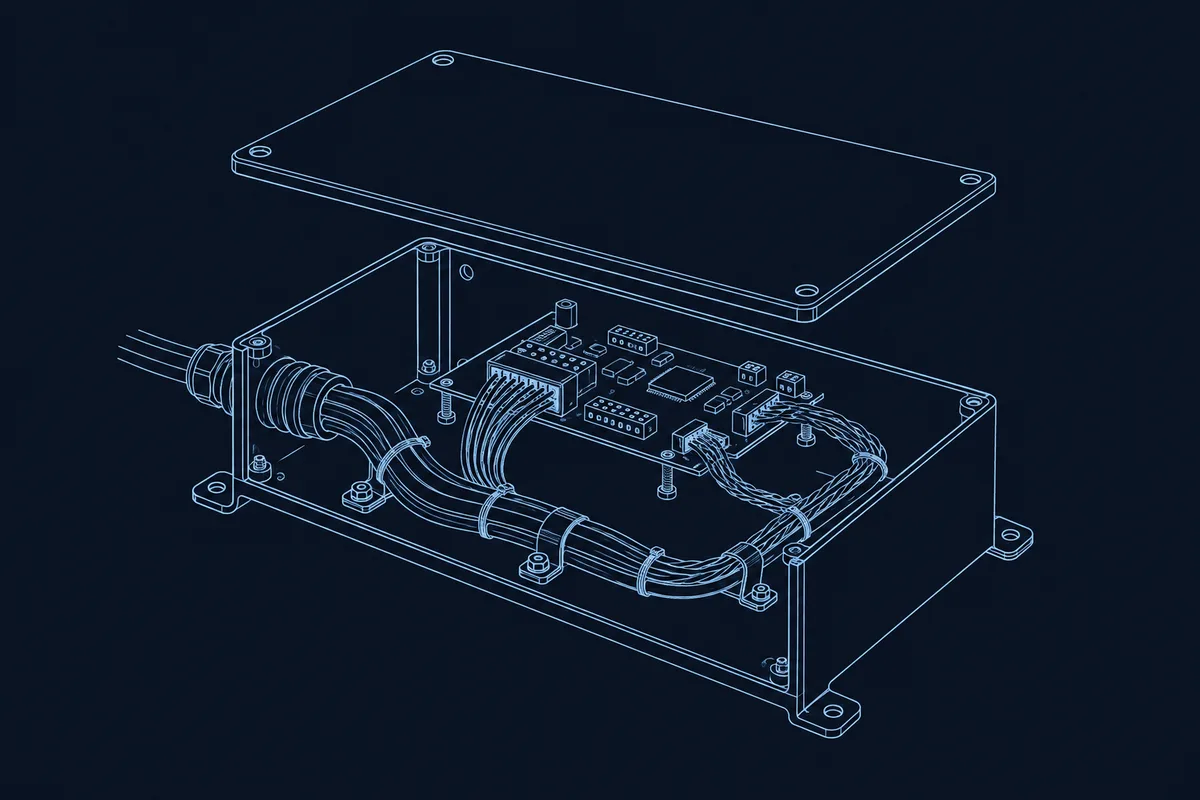
Cable management means designing the routes, fixing points, bend radii, separation, strain relief and identification into the enclosure and drawings before assembly. The result should be a harness that different operators can install and inspectors can check against the same requirements. A tidy bundle is useful, but appearance alone does not define an acceptable route.
This guide covers cable management and wire routing in enclosures for box build: the enclosure plus its electronic and mechanical assembly. The focus is the enclosed assembly supplied to an OEM, whose complete equipment and application requirements define the interfaces. Start with the approved cable specifications and turn each routing decision into a drawing callout.
Review the route from three perspectives
- Design: Can each cable reach its connector while meeting bend, separation, thermal and service-access requirements? Review the harness with board orientation and enclosure geometry; PCBA integration depends on those interfaces.
- Manufacturing: Can an operator install the harness in the intended sequence, reach the clips and connector latches, and close the cover without moving the approved route? Put locating features and inspection views into the build package.
- Procurement: Does the quotation identify the cable and retention hardware, revisions, supply responsibility and acceptance evidence? Treat a proposed substitute as a design review item, including its diameter and bend requirements.
Use these questions during cable harness integration planning, before enclosure details are released.
Common problems, consequences and design responses
This review table summarizes the constraints and manufacturer guidance discussed below; the responses are drawing recommendations, not universal dimensional limits.
| Common problem | Possible consequence | Design response |
|---|---|---|
| Bend tighter than the cable permits | Kinking or cable damage | Reserve the specified radius and review connector exit direction |
| Route against a sharp panel edge | Jacket or insulation abrasion | Relocate the route; specify a grommet, edge protection or protective sleeve |
| Long parallel power and signal runs | Noise coupling into sensitive circuits | Separate routes and minimize shared parallel length |
| Missing strain relief | Cable pull reaches contacts or terminations | Provide a rated retention feature and structural load path |
| Bundle crushed by ties or the cover | Cable damage or a displaced route | Control tie tension and check the closed-cover envelope |
| Cable beside a heat source | Exposure beyond its temperature rating | Define a keep-out region and check local operating conditions |
| Missing identification or service allowance | Unclear endpoints or difficult disconnection | Specify readable labels and a controlled service loop |
Bend radius: use the selected cable’s data
Minimum bend radius is often expressed as a multiple of cable outside diameter, or OD, with different values for fixed and moving installations. For example, LAPP’s ÖLFLEX FD 891 CY, article 1027104 specifies 4 × OD stationary and 7.5 × OD for dynamic continuous flexing. HELUKABEL’s HELUCHAIN HELUKAT 600S CAT.7 S/SFTP TPE likewise lists 4 × outer diameter fixed and 7.5 × outer diameter flexible. These are product-specific examples, not permission to use those factors for another cable.
Select the requirement for the actual installation, including any movement during use. If the datasheet omits it, obtain the manufacturer’s guidance before releasing the route. Also check the connector’s exit geometry and any required straight length before the bend.
Hypothetical calculation: assume a cable has an OD of 6 mm and its own datasheet requires a static minimum radius of 10 × OD. Assume the proposed layout requires a 90° turn within the enclosure’s 55 mm clear depth, which limits the available radius to no more than 55 mm.
| Check | Calculation or result |
|---|---|
| Required minimum radius | 6 mm × 10 = 60 mm |
| Available radius in this assumed layout | At most 55 mm |
| Minimum shortfall | 60 − 55 = 5 mm |
| Decision | Does not fit this route |
This is a geometric screening example, not a cable recommendation. The connector body, cable thickness and tolerances need additional space; cavity depth alone cannot judge every possible routing orientation. Consider a right-angle cable-exit connector, an approved cable with a different OD, or a revised connector and enclosure layout. Recheck electrical, thermal and termination requirements before changing cable size.
Strain relief and cable entry
Design a mechanical path that transfers cable pull into a gland, strain-relief fitting or properly specified clamp and its mounting structure. Do not make the crimp or solder joint carry that load. LAPP’s strain-relief guidance describes external forces being absorbed by the supporting structure so that contacts and internal electronics are protected.
Cable glands can combine retention with sealing. Specify the selected part, compatible cable diameter, panel interface and installation instructions. An internal routing clip and an entry seal have different jobs: verify the required function of each selected component. For sealing requirements, use the companion guide to IP ratings and ingress protection rather than assuming a neat entry is a sealed entry.
For harness workmanship, IPC/WHMA-A-620 covers materials, methods, tests and acceptance criteria for crimped, mechanically secured and soldered interconnections and associated cable/harness assembly activities. State the agreed revision and applicable acceptance requirements in the purchase package. This workmanship reference does not replace the product’s routing drawing or define an enclosure IP result.
Separate power and sensitive signals
Long, close parallel runs provide an opportunity for noise coupling. Give switching-power and sensitive signal cables separate planned paths; where they must cross, aim for 90° and minimize overlap. These principles appear in Rockwell Automation’s electrical-noise design guide, including its guidance for confined spaces.
Use the specified twisted-pair or shielded construction where the interface requires it. Rockwell’s PWM-drive wiring guidance includes shielded twisted-pair signal wiring and right-angle crossings; its drive-specific distances should not become a generic enclosure rule. Set separation from the EMC requirements, equipment instructions and cable specifications. Record shield termination locations and methods, with the boundary details covered in EMI/EMC shielding in box build enclosures.
Fix bundles without damaging them
Use ties for bundling and clips or clamps to locate the route, selecting each for the cable, load and environment. Avoid tightening until the insulation deforms. HellermannTyton’s application-tool guidance explains adjustable, repeatable tension as a way to avoid damaging bundled materials. Define the approved installation method rather than leaving tension to operator preference.
Adhesive bases require their own review. HellermannTyton’s mounting instructions identify adhesive selection, operating temperature, surface preparation, load direction and bonding time as relevant factors. Where those conditions cannot be controlled, consider a mechanically retained mount.
Keep cables away from sharp edges; specify protective sleeving where needed and a suitable grommet or edge strip at panel passages. Essentra’s grommet guidance describes protection against edges cutting into sheaths and insulation. Keep the route outside defined heat-source zones and compare local temperatures with the selected cable and fixing-part ratings.
Dimension locating points, channels and clip positions on the mechanical drawing. Reserve a service loop for the intended disconnection or panel-opening operation, and show where the surplus length is retained. Check that it maintains bend limits, clears the cover and stays out of fans, seals and connector latches.
Make assembly and inspection repeatable
Provide a routing drawing plus revision-controlled photo work instructions showing branch points, connector orientation and the route before cover installation. Mark tie spacing or individual tie positions on the drawing; establish them for the actual harness and support conditions.
At first-article inspection, compare the installed path with the released drawing: cable identity, bends, fixing locations, strain relief, separation, shield termination, endpoint labels and service loops. Check cover closure and any intended panel movement. Define subsequent production checks and any electrical or retention tests in the acceptance plan, with methods and limits agreed in advance.
Use endpoint labels that remain readable after installation. Where traceability is required, define how harness part/revision and inspection records connect to the enclosure assembly’s serial number. Coordinate that scheme with labeling, serialization and packaging. An approved first article should establish the reference route for subsequent builds, with changes controlled through the drawing revision.
What to put on your drawing / RFQ
- Cable list: manufacturer, part number, revision, endpoints, length and supply responsibility.
- Bend constraints: OD, minimum radius, static or moving condition, and connector exit requirements.
- Fixing points: dimensioned clips, channels, mounts and tie locations or spacing.
- Entry and strain relief: gland, clamp, panel interface, installation instructions and required checks.
- Separation: power/signal routes, crossing locations, shield terminations and thermal keep-outs.
- Identification: endpoint text, label material, placement and any serialization linkage.
- Allowance: service-loop location, retained surplus length and the operation it must accommodate.
- Acceptance: drawing and photo revisions, first-article checks, test scope and approval responsibility.
Use the box build RFQ checklist to package these inputs with the BOM and enclosure CAD. The capabilities hub shows where harness work connects with the other assembly steps.
FAQ
Can we specify one bend-radius multiplier for every cable?
Use each approved cable’s specification and installation condition. A common drawing value is acceptable only after engineering confirms it satisfies every affected cable and connector constraint.
Can the assembler decide the final route during the pilot build?
The pilot can resolve an open route, but record the result, review the constraints and approve the drawing and work instructions before using it as the production reference.
Is a cable gland enough strain relief for a board connector?
Review the full load path. The entry gland may retain the external cable, while the internal branch still needs support and allowance to avoid loading the board connector during assembly or service.
How much extra cable should we request for maintenance?
Define the service operation first, then establish the length and retained loop through a layout or prototype check. Avoid an arbitrary allowance that has nowhere controlled to sit.
What must be rechecked when purchasing substitutes a cable?
Review OD, bend radius, electrical and temperature ratings, shielding, gland fit and connector compatibility. Update affected documents and obtain the required approval before the substitute enters the build.