Menu

What We Build

Test and Measurement Equipment Box Build Assembly

Integrate instrument electronics, controls, interfaces, configuration and project-defined verification into a documented finished unit.

  • Controlled interface alignment
  • Approved configuration and test
  • Documented instrument handover

Request a quote

Request a Box Build Scope Review

Send your drawing, BOM or idea — we reply with a practical Box Build scope review.

Need technical help instead? Contact support

What Test and Measurement Builds Usually Involve

Test and measurement equipment often combines an enclosure or chassis with approved processing, acquisition, power and interface PCBAs; displays or indicators; switches, encoders or keypads; internal harnesses; fans, shields or thermal parts; and external signal, power or communication connectors. The Box Build scope brings these elements into the intended mechanical stack, loads the approved configuration and verifies the complete unit against the customer-defined acceptance method.

Measurement performance is not assumed from correct assembly. Accuracy, calibration, signal quality and product compliance depend on the approved design and a project-specific verification plan. Our scope records the integration and test evidence that has been expressly defined for delivery.

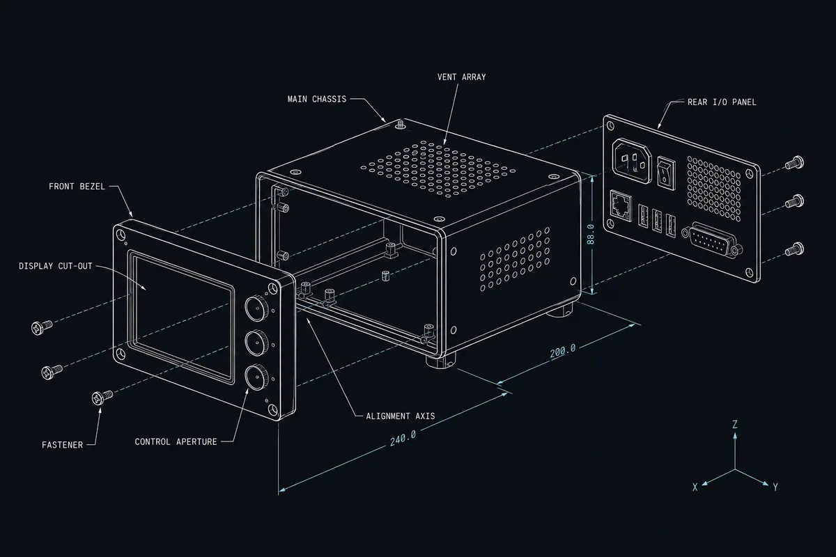
Exploded test instrument blueprint showing the enclosure, display, approved electronics and internal interfaces

Typical Integration Scope

Chassis, panels and controls

We integrate the approved enclosure, front and rear panels, bezels, handles, feet, racks or mounting hardware, shields, seals and internal supports. Control and connector openings are checked for alignment, fastener access, label space and serviceability through the enclosure integration plan.

Boards, displays and power

Approved PCBAs, modules, displays, power supplies, fans and thermal interfaces are installed in the released sequence. PCBA integration coordinates board support, isolation, connector access, grounding and any sensitive mechanical interface identified by the design.

Signal and internal cabling

Harnesses, coaxial leads, ribbon cables and other approved interconnects are routed to the customer definition. Retention, bend radius, connector seating, shielding, grounding, separation and strain relief are inspected where specified, with attention to routes near fans, edges and service points.

Configuration, identity and packaging

Approved firmware, settings and device options can be loaded and recorded. Unit identity, interface labels, warnings and serial data are applied from controlled artwork, followed by accessories, manuals, protective materials and the agreed final pack-out.

Engineering and Verification Considerations

Instrument builds require careful control of physical interfaces and test conditions. The released package should distinguish assembly workmanship checks, finished-unit functional checks and any product-performance or calibration activity.

Signal, thermal and service interfaces

Connector torque, shielding contact, cable routing, grounding, airflow, heat-sink contact, display alignment and access to replaceable parts can affect the delivered configuration. Critical characteristics should be called out in drawings or instructions, with a defined inspection method and authority for disposition.

Functional verification and calibration boundary

The functional-test package should identify test interfaces, reference assets, software, warm-up or setup conditions, stimuli, expected responses, limits and result fields. If calibration or a calibration record is required, the method, equipment responsibility, traceability basis and acceptance authority must be separately specified.

An NPI or pilot build can confirm panel fit, control feel, display and connector presentation, closure order, software loading, test access and packaging protection before repeat builds. Approved findings should update all affected product and process files.

What to Include in the RFQ

A useful RFQ shows what the instrument must contain, how it is assembled and configured, and which evidence supports final acceptance.

Product definition

BOM, approved sources, assembly drawings, enclosure CAD, panel drawings, variants, quantities and customer-supplied material.

Interface package

Board and harness revisions, connection maps, grounding and shielding requirements, thermal details, controls, displays and external interfaces.

Software and verification

Firmware, settings, loading method, inspection criteria, functional-test or calibration procedure, fixtures, reference responsibility, limits and data format.

Handover condition

Serial rules, label artwork, required records, accessories, manuals, protective packaging, compliance boundary, forecast and requested timing.

Use the Box Build RFQ checklist, review the capability map, or return to all product types.
Ready to Review Your Box Build Scope?

Have a BOM, assembly drawings, enclosure CAD, harness requirements or test procedure? Send what you have. We’ll confirm the Box Build scope, identify missing information and outline the next step before quotation.