Before installation
Confirm PCBA part number and revision, visible condition, mounting pattern, orientation, handling notes and mating components.
Board-to-System Integration
Install approved PCBAs into complete units with controlled mechanical, electrical, thermal and verification interfaces.
Request a quote
Send your drawing, BOM or idea — we reply with a practical Box Build scope review.
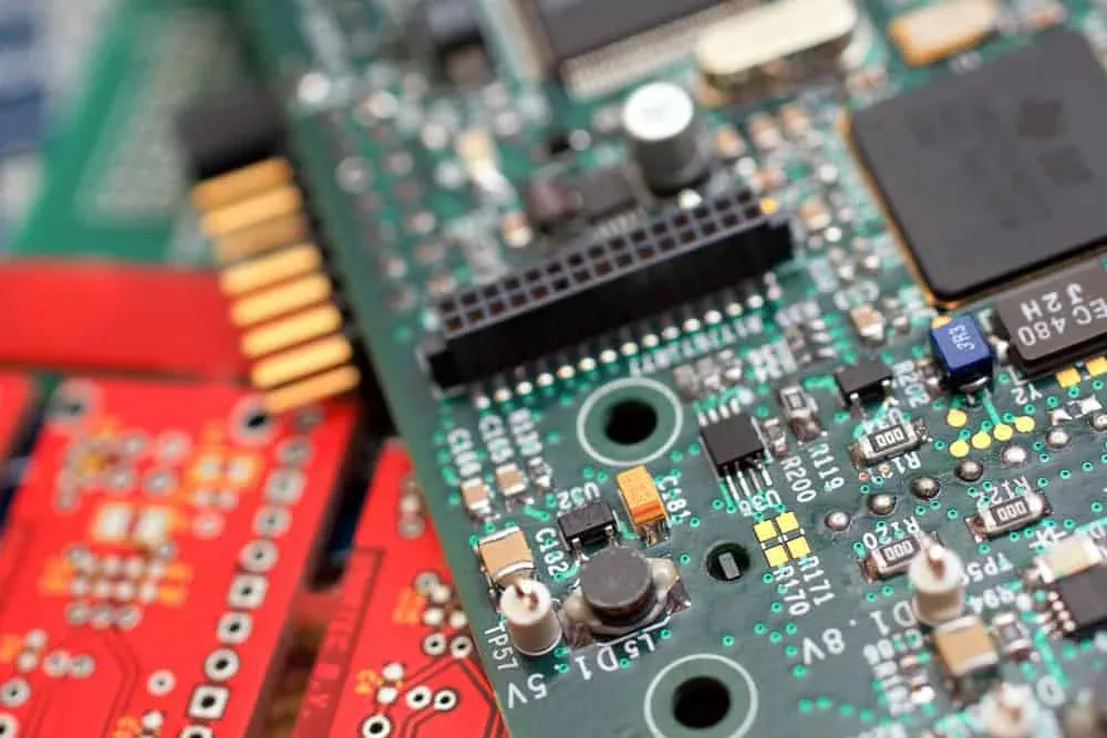
Our integration scope starts when the PCBA definition and supply status are approved for the build. We confirm the board identity and revision, install it into the mechanical assembly, connect it to power, controls, external interfaces and internal harnesses, load approved configuration where required, and verify the finished unit against the agreed test procedure.
This boundary keeps the quotation clear. Board fabrication and board-level process claims are not substituted for complete-unit evidence. If PCBAs are customer-supplied, the responsibility matrix also defines incoming checks, handling, shortage reporting and the disposition of boards that cannot enter assembly.
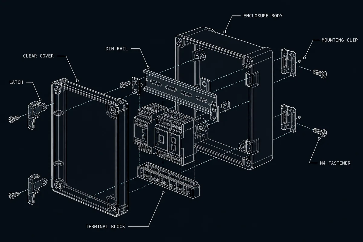
The board is installed to the approved mechanical stack. We review standoff height, fastener selection, board support, keep-out areas, electrical clearance, isolation features and the order in which the assembly must be built. The goal is a repeatable installation that does not force connectors into alignment or place avoidable stress on the board.
Confirm PCBA part number and revision, visible condition, mounting pattern, orientation, handling notes and mating components.
Follow the defined sequence, hardware callouts, fastening requirements, isolation points and inspection hold points.
A connector that fits in CAD may still be difficult to mate, inspect or service after surrounding parts are installed.
We check connector presentation at panel openings, mate and unmate space, latch access, cable exit direction, service-loop allowance and test access. These checks are coordinated with the enclosure and internal harness rather than reviewed as separate parts.
Where access cannot meet the approved design, the issue is recorded for engineering disposition before repeat builds continue.
We install customer-defined chassis bonds, grounding hardware, heat sinks, fans and thermal interface materials as part of the approved assembly. The scope should define contact surfaces, material or part identity, compression or fastening requirements and inspection criteria. We do not infer EMC or thermal performance from assembly alone. Any performance target needs an approved design and a project-specific verification method.
The connection plan identifies each endpoint, connector orientation, keying, polarity, cable label and route. Work instructions can include approved reference images and inspection points where they add clarity. Connectors are seated and retained according to the defined method, while routes are checked for sharp edges, heat sources, moving parts and loads transferred into the board.
After installation and connection checks, we test the assembled product to the approved finished-unit procedure. Depending on the project, this may include defined power-up behavior, boot status, indicators, controls, communication interfaces or selected I/O functions. Test software, limits, fixtures, data output and acceptance authority must be supplied or agreed during scope review.
The test record can associate unit identity, PCBA revision, firmware or configuration revision, procedure revision, result and approved exceptions. Failure handling defines isolation, engineering feedback, authorized rework and retest. Learn more about functional testing and traceability records.
Part number, revision, outline, mounting points, keep-outs and approved source or supply responsibility.
Standoffs, support, isolation, fasteners, panel alignment and service-access requirements.
Connector map, polarity, power sequence, grounding and approved mating parts.
Heat-transfer parts, fan interfaces, sensitive areas and handling instructions.
Approved image, version rules, programming access, device settings and identity data.
Finished-unit procedure, limits, fixtures, data fields, failure workflow and acceptance authority.
Include current revisions and identify incomplete items. The Box Build RFQ checklist provides the full product-level input list.
No. This scope begins with an approved PCBA and covers its installation, connection, configuration and system-level verification inside the finished Box Build.
Yes. Customer-supplied boards can be included when part identity, revision, incoming condition, quantities and handling responsibilities are defined in the scope.
The approved board revision is tied to the BOM, assembly instruction and applicable firmware or test revision. Changes require an agreed effective point and disposition for affected units.
Testing follows the customer-approved finished-unit procedure. It can include defined power-up, boot, I/O and functional checks, but coverage and pass or fail limits are set for each project.
The PCBA manufacturing resources behind these Box Builds operate under independently audited, currently valid management-system registrations. The certificates below are the genuine documents — shown in full for verification rather than as institution logos. Product-level compliance for a specific device (for example medical or automotive product approvals) remains defined and owned by the customer.
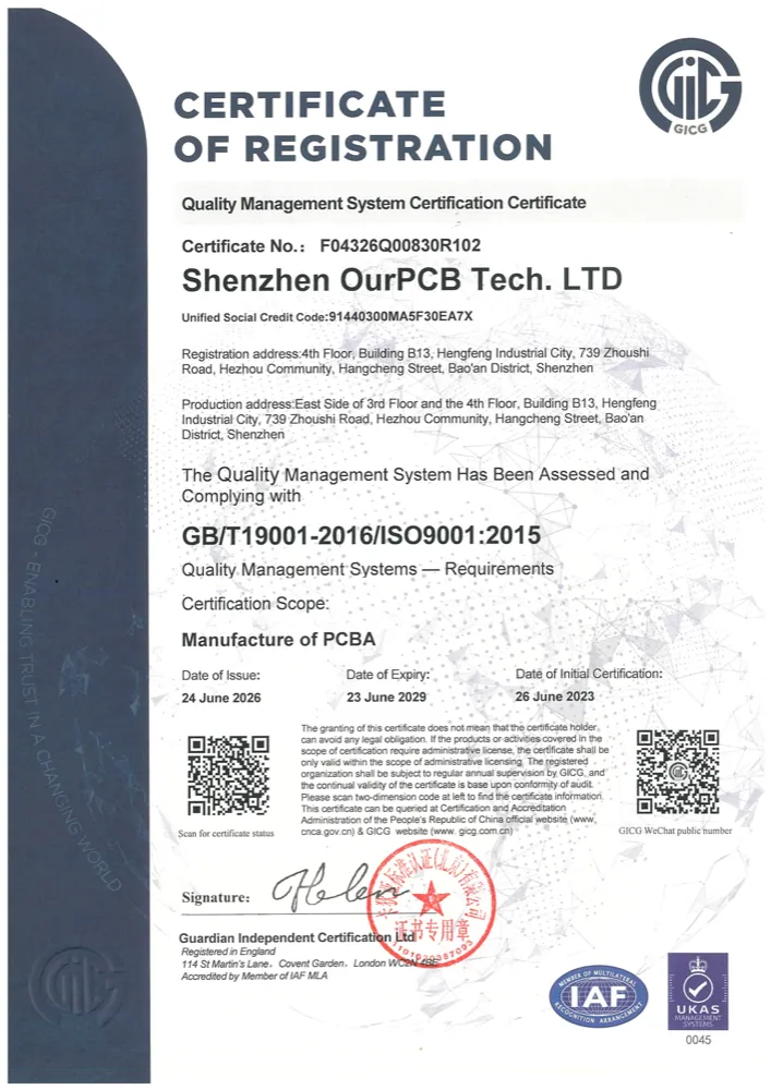
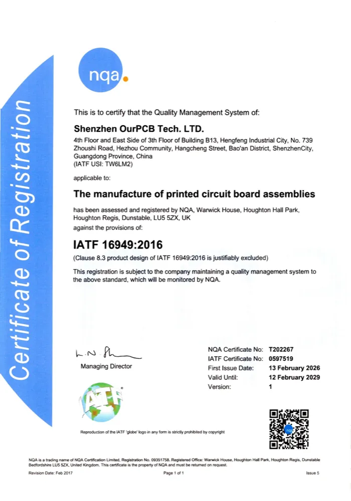
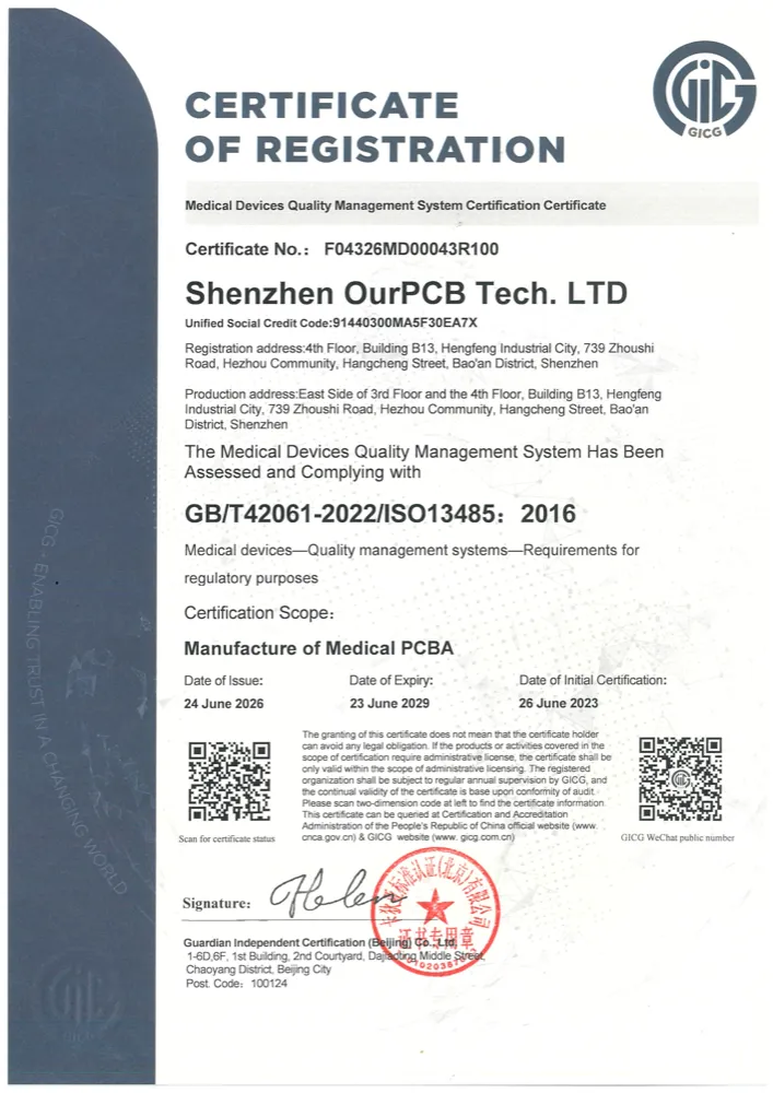
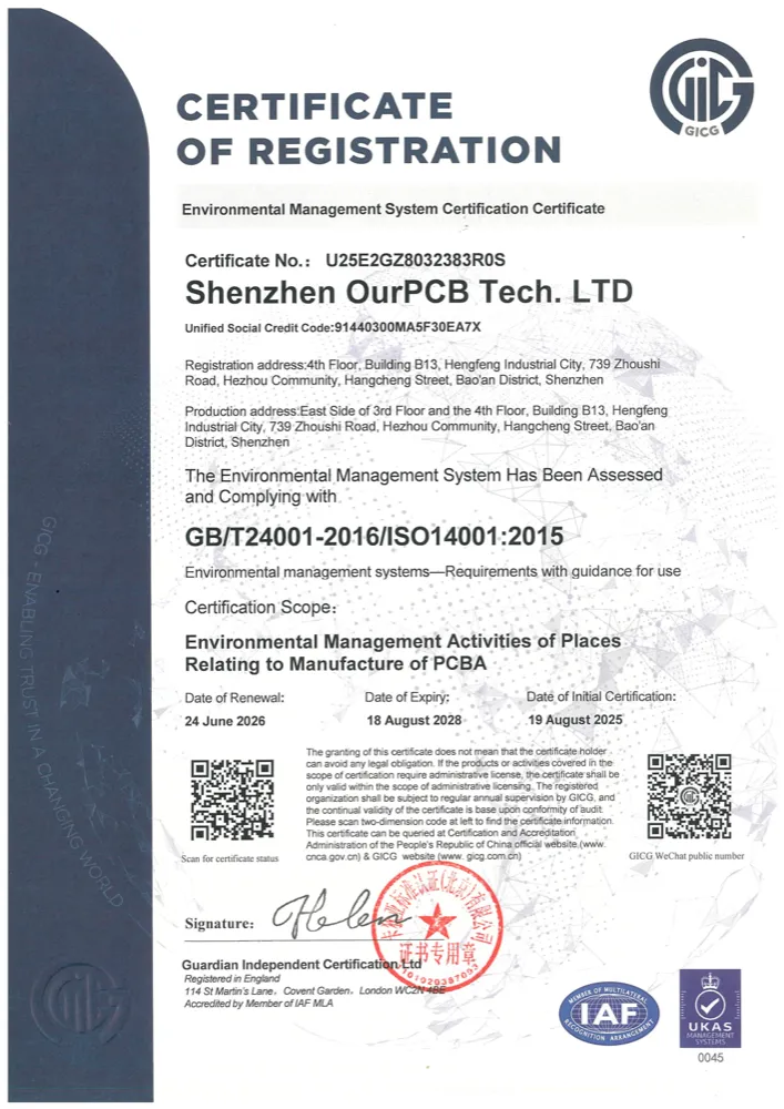
Certificates are issued to the operating manufacturing entity named on each document. Click any certificate to open the full-size scan.
Have a BOM, assembly drawings, enclosure CAD, harness requirements or test procedure? Send what you have. We’ll confirm the Box Build scope, identify missing information and outline the next step before quotation.

Send your drawing or idea and we’ll reply with a practical Box Build scope review.