Menu

What We Build

EV Charging Station Enclosure Box Build Assembly

Integrate the approved enclosure, power electronics, internal wiring, connector interfaces and verification into a defined finished charging unit — built to your released design.

  • Complete charging-unit integration
  • Project-defined power-up and I/O checks
  • Serialized and documented handover

Request a quote

Request a Box Build Scope Review

Send your drawing, BOM or idea — we reply with a practical Box Build scope review.

Need technical help instead? Contact support

What EV Charging Enclosure Builds Usually Involve

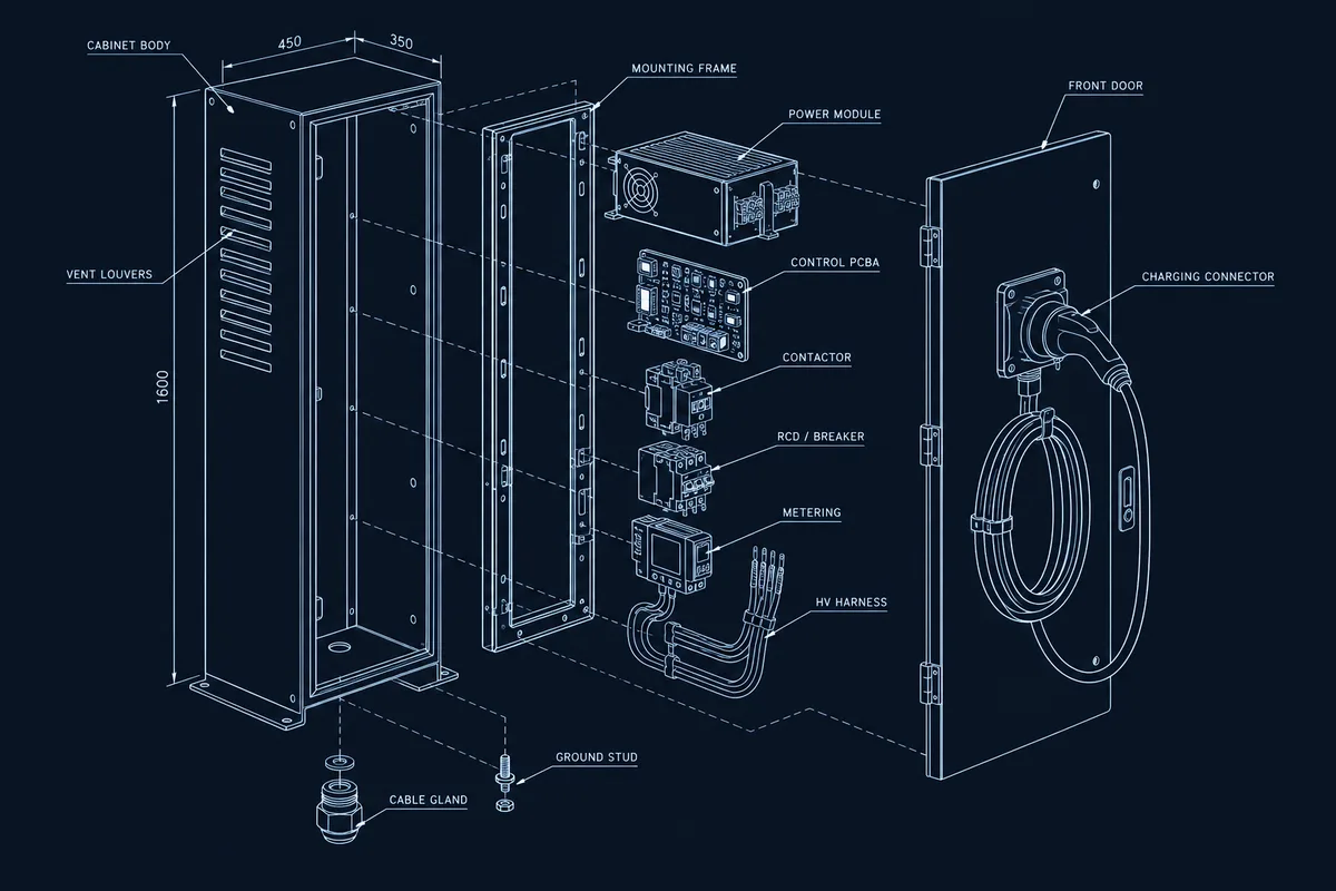
An EV charging station enclosure brings the approved cabinet or wall-box housing, mounting plate or internal frame, approved power modules and PCBAs, contactors, protection devices, metering, cable harnesses, terminals, the charging connector or socket interface and external I/O into one controlled assembly. The product definition determines which elements are customer-supplied and which we coordinate. Our role is to integrate the approved inputs, verify the finished unit against your acceptance plan and deliver it in the agreed condition.

The assembly sequence matters because access narrows as rails, boards, power devices, ducts and high-current harness branches are installed. A build plan should keep fastening, connector mating, grounding, sealing, inspection and service access possible without forcing parts or hiding required checks. It is closely related to how we handle power control systems, energy storage / BESS enclosures and industrial control boxes.

Exploded EV charging station enclosure blueprint showing the cabinet body, mounting frame, power module, control PCBA, contactor, protection devices, high-current harness and front charging connector

Typical Integration Scope

Enclosure and mechanical platform

We prepare the approved indoor or outdoor housing and internal mounting structure, then install rails, brackets, panels, seals, glands, grounding hardware and the connector or socket interface. Cutouts, ingress sealing for the rated environment, cable-entry and door or cover clearances are checked as part of enclosure integration.

Power electronics and protection

Approved power modules, PCBAs, contactors, breakers, residual-current or protection devices, metering, terminals and control boards are installed to the released assembly definition. Mounting, isolation, creepage and clearance presentation, thermal contact and access are coordinated through PCBA integration and electromechanical assembly — to the design you provide, not one we specify.

Internal interconnections and high-current wiring

Power and signal harnesses follow the approved connection map, with attention to conductor sizing per print, bend radius, separation, strain relief, retention, sharp edges, heat sources, grounding and bonding. Connection and polarity checks are defined with the harness integration scope.

Configuration and final delivery

Where required, approved firmware or device parameters are loaded and recorded. Unit labels, serial identity, warnings, accessories, manuals and protective packaging are applied according to customer-approved files before the finished assembly is released.

Engineering and Verification Considerations

Review focuses on the interfaces that affect assembly repeatability and finished-unit behavior. Requirements are not inferred from the product category — they must be defined by the drawings, specifications and customer-approved acceptance plan.

Layout, clearance, sealing and environment

The design should identify electrical clearances and creepage, grounding and bonding points, ventilation or thermal paths, the ingress-protection rating and sealing for indoor or outdoor use, orientation, mounting method and any environmental constraints. Product-level safety and EV charging certification — for example the type approval and standards that govern the charger itself — remain the customer's responsibility and are separate from assembly verification; they should be assigned in the responsibility matrix.

Finished-unit test

A project may require defined power-up behavior, voltage and continuity observations, grounding checks, indicators, controls, communications or selected I/O checks. The functional-test package must state setup conditions, fixtures, limits, expected responses, pass or fail rules, data capture and the process for failures, rework and retest.

For a new or changed design, an NPI or pilot build can expose access, routing, sealing, sequence and test issues before repeat production. Approved findings feed back into the BOM, drawings, work instructions and verification package.

What to Include in the RFQ

Send the current product definition and mark preliminary information clearly. The most useful package explains both the physical build and the evidence required at handover.

Product and material definition

BOM, approved sources, quantities, variants, assembly drawings, enclosure CAD, environmental rating, panel details and a list of customer-supplied items.

Electrical and software inputs

Connection diagrams, power and PCBA and harness revisions, conductor sizing, grounding and bonding requirements, firmware, configuration values and programming access.

Verification and compliance boundary

Inspection criteria, functional-test procedure, fixtures, acceptance limits, required records and clear ownership of product-level and certification activities.

Identity and delivery

Serial rules, label artwork, accessories, manuals, packaging, delivery condition, build quantity, forecast and requested timing.

Use the complete Box Build RFQ checklist or return to all product types.
Ready to Review Your Box Build Scope?

Have a BOM, assembly drawings, enclosure CAD, harness requirements or test procedure? Send what you have. We’ll confirm the Box Build scope, identify missing information and outline the next step before quotation.