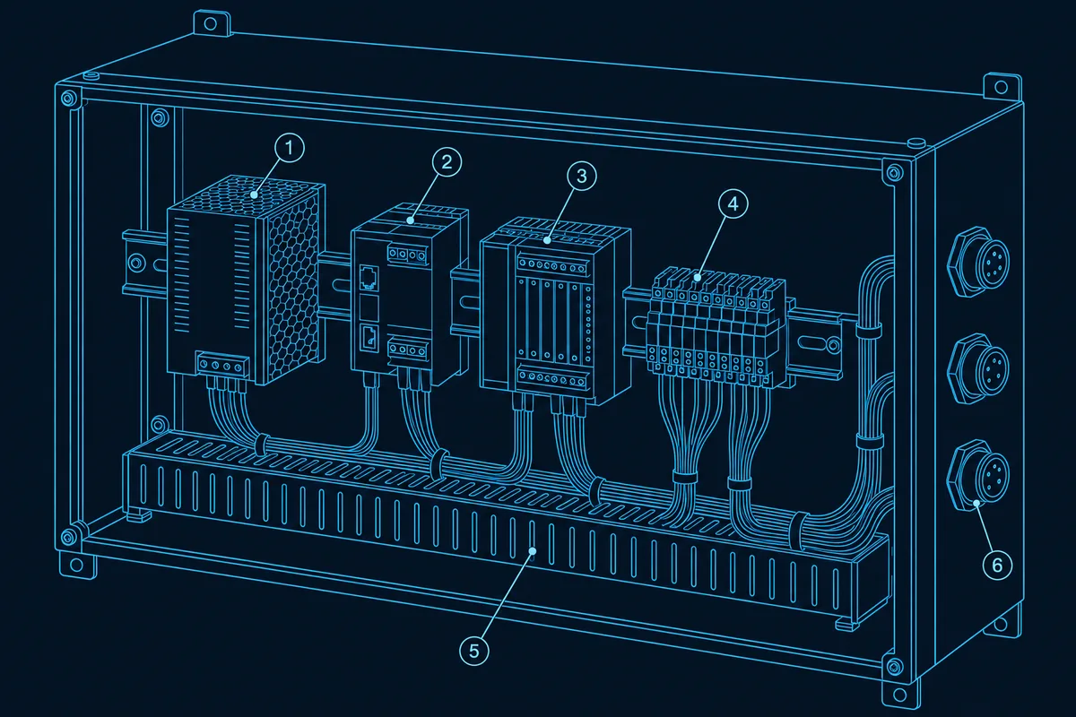
An industrial automation box build is judged by how it behaves after installation: on a 24 V DC supply that sags and recovers, next to drives and contactors that generate noise, on a DIN rail inside a cabinet with limited air, for years of service. A drawing and a BOM are not enough to cover that. Beyond them, five things belong in the RFQ: the electrical supply window, the EMC environment, the mounting and wiring conventions, the serviceability and lifecycle plan, and the evidence you want back with each unit. This guide covers each one, with arithmetic you can reuse.
It builds on the general guides to preparing a box build RFQ package and a quotable BOM; here the focus is what is specific to industrial control and automation enclosures. Our industrial control boxes page describes what that kind of build usually involves.
Decide what the box is before you quote it
The same enclosure can fall under different rules depending on what it is. A common summary is that UL 508A treats a panel as a listed product in North America, NFPA 79 treats it as part of an industrial machine, and IEC 61439 treats it as a low-voltage power distribution assembly with its own verification (control panel standards overview). They draw different boundaries, so say in the RFQ which regime your end customer or market requires.
Whether a given box-build supplier is set up to build to a listing program is a question to ask, not something to assume. Our own scope for control boxes is integration of approved inputs: electronics, wiring, terminals and interfaces are built to your drawings, then verified and handed over as agreed. If a listing mark or a panel-shop approval is needed, state it up front so the right supplier is quoted.
Specify the five things that change in industrial service
| Topic | What to put in the RFQ | Why it matters in a plant |
|---|---|---|
| Supply window | Nominal voltage, allowed range, ripple and dropout tolerance of each module | The 24 V rail is shared; a drop at the far end can reset a controller |
| EMC environment | Which generic or product-family standard applies and what the enclosure sits next to | Drives, contactors and relays create the noise the box must tolerate |
| Mounting and wiring | Rail type, module layout, terminal types, ferrule and labeling requirements | Technicians service it years later, often under time pressure |
| Serviceability and lifecycle | Replaceable modules, spares, approved alternates, revision control | Plant equipment outlives many component lifecycles |
| Evidence | Test record per serial, loaded configuration or firmware version, labeling check | Lets you accept units without opening them |
Design the 24 V DC feed to the standard window
Most control equipment in an enclosure runs from a 24 V DC rail. PLC equipment built to IEC 61131-2 is specified over an absolute supply range of 19.2 to 30 V DC including ripple, with ripple below 5% and tolerance of supply interruptions shorter than 10 ms. These values appear in PLC data sheets that cite the standard, for example ABB’s technical data. Your own modules can differ, so read each module’s data sheet and design to the narrowest window among them.
The wiring from the supply to the load eats into that window. For a copper conductor, resistance is resistivity times length divided by cross-section, and a DC feed has a go and a return path. Using 0.0172 Ω·mm²/m for copper at 20 °C:
| Assumed case | Round-trip length | Resistance | Current | Voltage drop |
|---|---|---|---|---|
| 1.5 mm² feed, supply 2 m from the load | 4 m | 0.0172 × 4 ÷ 1.5 = 0.046 Ω | 5 A | 0.23 V |
| 0.75 mm² feed, supply 10 m from the load | 20 m | 0.0172 × 20 ÷ 0.75 = 0.459 Ω | 4 A | 1.83 V |
These cases are assumptions to show the method, not recommendations. The second case leaves the load at about 22.2 V when the supply is set to 24.0 V. That sits inside a 19.2 V floor with room to spare, but the same wire carrying a motor-start inrush for a fraction of a second drops further, and the margin is shared with everything else on the rail. State the maximum acceptable drop at the farthest load in the RFQ, and let the wire size follow from it.
Plan the DIN rail and terminal layout
The common mounting rail is the 35 mm top-hat rail, specified in IEC/EN 60715 in a 7.5 mm and a 15 mm depth. Modular devices are sized in 18 mm module widths, so a one-module breaker is 18 mm and a four-module device is 72 mm (DIN rail overview). The same source notes that rails are for mechanical support and are not used as a conductor, although they may provide a chassis grounding connection.
As an assumed layout, eight single-module breakers take 8 × 18 = 144 mm, a four-module power supply 72 mm and a five-module controller 90 mm, which is 306 mm of rail before end stops and the spacing that each device’s data sheet asks for. Put the rail length and the free-space rules on the drawing instead of leaving them to be inferred.
Layout rules worth writing down:
- Group by function. Power entry and protection, control, I/O, then field terminals, so a technician can read the panel left to right.
- Separate heat producers. Place power supplies and drives apart from heat-sensitive modules, and keep the air path clear; see thermal management in enclosures.
- Define terminal and wire preparation. Terminal type, wire ferrule requirement and tightening torque belong on the drawing, not in the supplier’s habits.
- Label for service. Every terminal, wire and device gets a label that matches the wiring diagram; see labeling and serialization.
Write down the EMC environment, not just the standard
IEC 61000-6-2 is the generic immunity standard and IEC 61000-6-4 the generic emission standard for industrial environments. Each applies where no dedicated product or product-family standard exists, so first check whether one does for your product (IEC 61000-6-2 overview; IEC 61000-6-4 overview). Then describe what the enclosure actually sits next to, such as variable-speed drives or large contactors.
The box-build side of EMC is workmanship that follows the design: keeping power and signal cables apart, terminating shields as drawn, and bonding the enclosure and mounting plate as specified. See EMI and EMC shielding in box build enclosures and cable management and wire routing for how those details are drawn. Compliance testing is a separate activity on the finished product, so agree who owns it and what, if anything, the supplier tests.
Plan for service and lifecycle
Industrial equipment is serviced, not thrown away. Ask for a design where a failed module can be replaced without disturbing the rest, connectors are keyed so they cannot be swapped, and a spares list names each part by manufacturer and part number. Industrial products also outlive many component lifecycles, so name an approved alternate on single-sourced parts and agree who is told, and how, when a part is discontinued. The same revision discipline applies to the BOM, the wiring diagram and any loaded configuration; see the BOM preparation guide and PCBA integration in box build.
Ask for evidence with every unit
The evidence you want back depends on the risk, so decide it before the build:
- Functional test record per serial number, against a test plan you have approved; see the functional test plan guide and our functional testing capability.
- Wiring verification such as continuity against the wiring diagram, and insulation or dielectric tests where your specification requires them.
- Configuration record: the firmware or configuration version loaded, if the supplier loads it; see firmware loading and configuration.
- Traceability from serial number to the lots of critical parts; see traceability and serialization.
RFQ checklist for an industrial automation box build
- Which panel or machine standard regime applies, and whether a listing mark is needed.
- The 24 V DC window, the narrowest module tolerance, and the maximum voltage drop at the farthest load.
- Rail type and depth, device module widths, rail length and free-space rules.
- Terminal types, ferrule requirement, torque values and labeling scheme.
- The EMC environment, the applicable standard, and who owns compliance testing.
- Cable routing rules: power and signal separation, shield termination, bonding.
- Spares list, approved alternates, and the obsolescence notification process.
- Test plan, records per serial, and configuration or firmware version to record.
Send the package through the request a quote page; a DFM and BOM review before quoting catches mismatches early. For power-side builds see power control systems, and for cabinets around robot cells see robotics controllers and automation cabinets.
FAQ
What is the difference between a box build and a control panel?
A box build is the broader job of integrating an enclosure with its electronics, wiring and interfaces into a finished product. A control panel is one kind of box build, and in North America it may be a listed product under UL 508A, while in machinery it may fall under NFPA 79. Say which applies, because it decides who can build it and what is verified.
Is 24 V DC always 24 V at the load?
No. IEC 61131-2 equipment is specified over a window of 19.2 to 30 V DC including ripple, and wiring adds a voltage drop between the supply and each load. Work out the drop for the longest run and check it against the narrowest module tolerance.
Does the DIN rail carry electrical current?
It is a mechanical support. It may provide a chassis grounding connection, but it is not used as a conductor for load current.
Who is responsible for EMC compliance of the enclosure?
Usually the product owner, because EMC is tested on the finished product in its intended environment. The supplier’s part is building the enclosure to the agreed drawing: routing, shield termination and bonding. Agree in the quote what is tested and by whom.
What should I ask for to accept units without opening them?
A functional test record per serial number against an approved test plan, the configuration or firmware version loaded, and the labeling and traceability records. Decide this before the build so the supplier can plan the test fixtures and records.