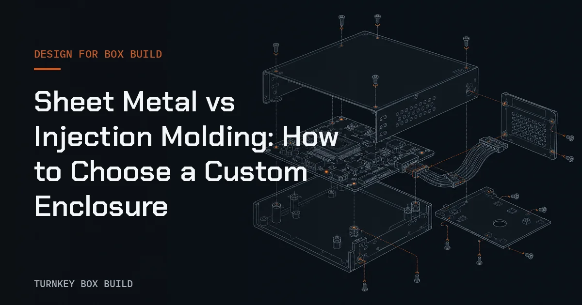
An enclosure is one input to a Box Build, but it influences almost every downstream operation: PCBA mounting, cable routing, grounding, thermal interfaces, connector access, labels, functional test, service, and packaging. Choosing between fabricated sheet metal and injection-molded plastic therefore requires more than comparing the enclosure piece price.
Both processes can produce effective housings. The better route depends on required material behavior, design maturity, expected demand pattern, geometry, tooling commitment, cosmetic expectations, and the evidence needed to accept the finished part. No universal volume threshold decides the answer; suppliers need the actual geometry, material, finish, tolerances, and forecast assumptions to compare the alternatives.
Compare the cost structures, not a generic volume rule
Sheet-metal fabrication normally builds the enclosure from flat stock using operations such as cutting, punching, bending, joining, inserting hardware, and finishing. It may need programming, bend tools, fixtures, or dedicated inspection aids, but it does not require a cavity mold for the complete part. That often makes design iteration more manageable before the enclosure is stable.
Injection molding requires a mold whose construction reflects the part geometry, resin, gate approach, ejection, cooling, surface texture, and any slides or other mechanisms needed for undercuts. The tooling commitment is higher, while repeated molding can become economical when demand is stable enough to spread that investment across accepted parts.
The quotation comparison should separate:
- one-time engineering, tooling, fixtures, and samples;
- recurring material, processing, secondary operations, and inspection;
- changes to drawings, tooling, finish, or inserts;
- expected tool maintenance and ownership terms;
- packaging needed to prevent cosmetic or dimensional damage;
- risk created by uncertain demand or an enclosure design that is still changing.
An injection-molded part is not automatically cheaper at “high volume,” and sheet metal is not automatically cheaper at “low volume.” Part complexity, utilization, secondary work, quality requirements, and commercial assumptions all affect the result.
Engineering trade-offs at a glance
| Decision factor | Fabricated sheet metal | Injection-molded plastic |
|---|---|---|
| Basic construction | Flat stock cut, formed, joined, and finished | Resin formed in a dedicated mold |
| Up-front commitment | Process setup, possible fixtures and standard or dedicated tooling | Product-specific mold and associated validation |
| Design changes | Drawing and program changes may be possible; changes that affect tooling or formed geometry still need review | Tool modifications may be limited, costly, or require replacement depending on the feature |
| Geometry | Well suited to panels, brackets, chassis, folds, and assembled structures | Supports integrated ribs, bosses, clips, textures, and complex contours when designed for molding |
| Wall design | Thickness begins with available sheet; bends and joining create local features | Relatively uniform walls generally support filling and cooling; ribs and bosses require careful proportioning |
| Conductivity | Metal can contribute to electrical bonding, grounding, heat spreading, and shielding when joints and finishes are designed accordingly | Most unfilled polymers are electrically insulating; thermal and shielding functions need material or added-feature decisions |
| Corrosion and chemicals | Performance depends on alloy, coating, cut edges, joints, and exposure | Performance depends on resin, additives, stress, temperature, ultraviolet exposure, and chemicals |
| Cosmetic control | Grain direction, welds, fasteners, bend marks, and coating need definition | Gate marks, ejector marks, parting lines, weld lines, sink, color, and texture need definition |
| Dimensional behavior | Bend variation, springback, joining, and coating can affect the final assembly | Shrinkage, cooling, orientation, moisture, and warpage can affect dimensions |
Material selection starts with the operating environment
“Metal” and “plastic” are families, not specifications. A sheet-metal decision still requires an alloy or grade, thickness, temper where relevant, and finish. A plastic decision requires a resin grade and any reinforcement, flame-performance, ultraviolet, color, or regulatory characteristics the product actually needs.
Start with operating temperature, mechanical loads, impact, chemicals, cleaning agents, moisture, sunlight, flammability requirements, electrical behavior, heat sources, and expected service conditions. Then identify which properties are essential and which are preferences. A material data sheet can support screening, but finished-part performance also depends on geometry, processing, joints, and the product’s real use conditions.
Metal is conductive, but an enclosure does not provide effective electromagnetic shielding merely because its panels are metal. Seams, apertures, coatings, fasteners, gasketing, and bonding paths influence the result (see EMI/EMC shielding in box build enclosures). Plastic is often insulating and can reduce mass or support integrated features, but shielding or heat spreading may require coatings, inserts, internal parts, or a different construction. Those additions belong in the cost and assembly comparison. When the electronics dissipate real power, the wall material also sets how much heat a sealed enclosure can shed; the thermal management guide shows how to estimate it.
Tolerances must match the process and the function
Do not copy a tolerance scheme from a machined metal part onto a molded plastic housing. Injection-molded dimensions are influenced by resin behavior, tool temperature, processing conditions, wall transitions, cooling, shrinkage, and warpage. The designer should identify the dimensions that control fit or function, establish suitable datums, and review them with the molder.
Sheet-metal assemblies have different contributors: material thickness, cut-feature accuracy, bend radius, springback, bend sequence, joining, inserted hardware, and coating buildup. A hole may be accurate in the flat pattern while its final relationship to another panel changes after forming and assembly. Functional requirements such as connector alignment, door closure, gasket compression, PCBA standoff position, and label clearance should be checked in the assembled condition.
For either process, tighter tolerances increase the need for process control and inspection. Apply them where product function requires them rather than to every dimension by default. The enclosure integration capability shows why mounting and interface dimensions need to be reviewed as part of the assembled product.
Design rules shape what each process does well
Sheet-metal designs need feasible bend radii, tool access, bend relief where required, allowance for springback, and a joining strategy. Designers also need to consider whether hardware is installed before or after finishing, how electrical bonding surfaces remain conductive, and how technicians reach fasteners and connectors during assembly.
Injection-molded designs normally need draft for release from the tool, a planned parting line, gate and ejection locations, and wall transitions that limit sink and distortion. Ribs and bosses can add stiffness or locate internal parts, but they must be designed with the molding process rather than added as if they were machined features. Undercuts may require tool actions that increase complexity.
In the Box Build, enclosure geometry must also support the PCBA integration sequence and the cable-harness routing and connection plan. A housing that looks complete in CAD may still create inaccessible screws, trapped cables, excessive connector loads, ambiguous grounding, or no safe route for test connections.
Surface finish is both cosmetic and functional
Sheet metal may be powder coated, painted, plated, passivated, anodized when the selected aluminum and design are suitable, or left with another specified finish. The drawing should identify protected contact areas, cosmetic zones, color and texture references, marking method, and acceptable appearance. Finish thickness can affect close fits, threads, hinges, connector cutouts, and grounding points.
Molded color and texture can be created through the selected resin and tool surface, but cosmetic outcomes still depend on material, gate location, flow, wall design, parting lines, and ejection. Painting, printing, labels, inserts, or shielding coatings are secondary operations and should be quoted as such.
Avoid using a finish name as the acceptance criterion. Define measurable dimensions where function depends on them and approved visual references where appearance is subjective. For outdoor, chemical, flammability, ingress, or electromagnetic requirements, specify the applicable product test and acceptance method rather than assuming the base process supplies a rating.
Prototype the questions that matter
A prototype should answer named questions. A 3D-printed housing can check space claim, access, basic fit, and user interaction, but it may not reproduce the mechanical, thermal, surface, or dimensional behavior of the production resin and molding process. A fabricated sheet-metal sample can expose bend, joining, finish, and assembly issues, but it does not validate a future molded design.
First articles and pilot builds should verify the released characteristics relevant to the selected route. In a Box Build context, that includes more than enclosure dimensions: install the actual or representative PCBA, harnesses, connectors, thermal parts, labels, and fasteners; follow the proposed sequence; and check access for inspection and test. Feed corrections back into drawings, bills of materials, work instructions, and test assets before production release.
Make the choice with a project-specific decision record
Document the decision so it can be revisited when demand or design changes. A useful record includes:
- required material and environmental behavior;
- enclosure geometry and functional dimensions;
- expected demand pattern and product life assumptions;
- design maturity and likely change areas;
- tooling, maintenance, ownership, and change terms;
- finish, marking, and cosmetic acceptance;
- Box Build assembly, grounding, thermal, test, and service interfaces;
- prototype, first-article, and production acceptance evidence.
Put those inputs into the RFQ checklist and ask both fabrication and molding suppliers to state assumptions, exclusions, and design concerns. The enclosure choice is complete only when it supports the finished Box Build, not merely when an isolated housing can be manufactured.