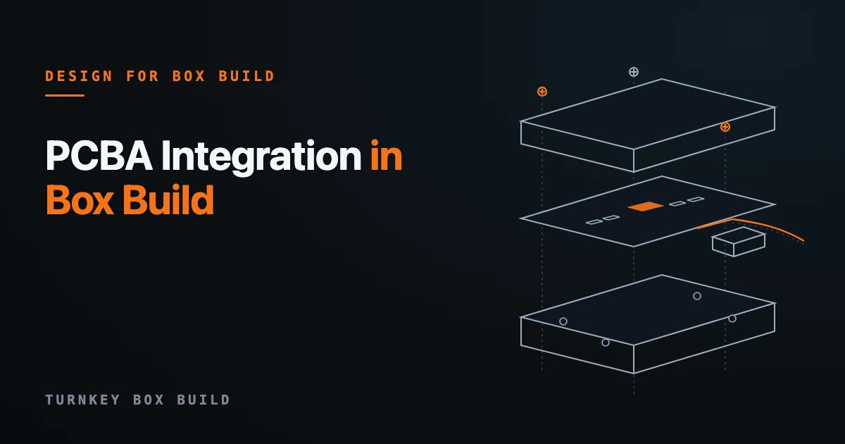
PCBA integration in box build means installing an approved, populated board into the finished enclosure and making it work as a system — connected to power, harnesses, external interfaces, and its housing, then verified as a complete unit. The board fabrication and population happen upstream; integration begins when that PCBA is approved and ends when the assembled unit passes its agreed test. The deceptive part is that the board can pass its own electrical test and still fail once it is in the box, because the failures live in the interfaces, not the board.
This is a deep dive into those interfaces — where an in-spec PCBA still goes wrong during integration, and what to define so it does not. It complements the PCBA integration capability scope with the engineering detail behind it, and assumes the board-versus-system boundary set out in box build vs PCBA assembly.
The board passed ICT. That is not the same as working in the box
A PCBA that passes in-circuit or functional test on the line has been verified as a board, on a fixture, in free air. Integration subjects it to a different set of loads: mechanical mounting, a metal enclosure, a wiring harness, heat with no bench airflow, and mating connectors it never saw on the tester. Each is a place a good board can be turned into a field failure by the assembly around it. Treating integration as “just screw the board in” is what produces units that pass at board level and fail at system level.
Mounting: the board is a mechanical part now
Once a PCBA is bolted into a chassis it becomes a structural element, and the mounting can preload the board before it ever powers up. Over-torqued standoffs, an unsupported span under a heavy connector, or a fourth mounting boss that sits proud all flex the board — and board flex is transmitted straight into solder joints, especially under large BGAs and heavy through-hole parts. The right approach is defined standoff torque, a supported mounting pattern that does not warp the board, and orientation and clearance called out so the board cannot be installed reversed or foul a boss. Handling rules (ESD, edge-only handling, no press on populated areas) belong in the same instruction.
Grounding and EMI: the enclosure is part of the circuit
The moment the board is in a metal box, the chassis is part of its electrical environment. A missing or high-impedance chassis bond, a ground path that closes a loop through the mounting hardware, or a shield that is landed at the wrong point can turn a clean board into one that radiates or is susceptible. Integration has to define which mounting points are electrical grounds versus mechanical only, the bonding method, and where shields and drain wires terminate — decisions that are invisible on the board but decisive in the enclosure.
Thermal: bench airflow does not exist inside the box
A board validated on an open bench had convection the enclosure removes. Integration is where the real thermal path is made: heatsink or thermal-pad contact and pressure, the gap the pad actually fills, and airflow that a carelessly dressed harness can block over the hottest part. A thermal design that was fine in the lab fails in the box when the pad is under-compressed or a cable bundle sits across the intake. These are integration decisions, not board decisions.
Harness and connectors: the highest-density source of build defects
Most integration defects are wiring defects. A connector with the wrong keying or a reversible housing, a harness dressed so it strains a board-mounted connector, insufficient service loop, or mating that loads the board rather than the housing — each is an integration failure that no board test catches. Error-proofing is the fix: keyed and polarized mating so a harness cannot be installed backwards, defined routing and clamping so cable weight is off the board, and a mate/de-mate sequence in the instruction. The related cable and harness integration discipline is where most of this is controlled.
Configuration and system-level test
If the unit carries firmware or options, integration includes loading the approved configuration and recording that it matches the released revision. Then the test changes character: functional verification now exercises the assembled unit — power-up behavior, the interfaces as they are wired, and the finished-product acceptance criteria — not the board in isolation. What “tested” means has to be written for the integrated unit, because a board pass and a unit pass are different claims.
The other integration: the supply chain behind the box
Physical integration is only half of it. When the PCBA, the harness, and the enclosure come from separate suppliers, the integration team inherits every gap between them — mismatched revisions, connectors that were specified independently, and logistics that have to converge three deliveries before a unit can be built. Consolidating those under one box-build partner removes the cross-supplier seams that cause most first-build surprises.
Representative project (anonymized). An industrial OEM ran separate suppliers for its harnesses and its PCBAs, which left its integration team managing a fragmented supply chain, potential assembly misalignments, and complex logistics to converge the two. Bringing board assembly, harness, and integration under a single partner removed those cross-supplier gaps and let one team own the interfaces — and the relationship grew from five-figure harness orders into a broader, multi-category manufacturing program. The technical win (fewer integration defects) and the commercial win (one accountable partner) were the same decision.
What to define in the RFQ for clean integration
Clean integration starts in the quote. State the approved PCBA identity and revision and who supplies it; the mounting pattern and any torque or support requirements; grounding and shield termination points; the thermal interface and its target; the harness mating, keying, and routing; the firmware or configuration to load; and the finished-unit test method and acceptance criteria. The capability page’s RFQ inputs list these as a checklist. Defining them up front is what turns integration from a source of first-build surprises into a controlled step — the same discipline that separates a real box build assembly from a bag of parts and a hope.